SPY ROBOT
.
Assembling Robot car chassis
We are going to use smart robot car chassis for building our Spy Robot. It helps us in rapid prototyping our robot. All we need to do is assembling t
The base of the car kit is made up of acrylic sheet. It has many holes in it. So we can attach many components of our choice on this sheet. We can drill holes according to our choice aswell. A DC motor is attached to the yellow plastic hub with rubber wheel. The wheels don’t have a good grip but they are very suitable for indoor use. On the back of the plastic hub there is an axle. Tyre is mounted on this axle. The plastic hub has a gear box in it to reduce the speed of DC motor. This gear circuitry has a gear reduction ration of 1:48 with a speed of 125 revolutions per minute. There is also a battery holder with the car chassis. The motors have an operating voltage of anywhere in between 3V - 6V which makes them a good choice for an average robot. The motor does not come with wires attached so we will have to solder wires with the terminals of the DC motor. There is also a castor wheel that is attached at the front of the robot chassis. The caster wheel and plastic gear hub has 4 mounting holes to attach them to the car chassis. There is also another separate small bag that contains the smaller pieces including nuts and bolts. There are also encoders disks made up of black acrylic sheet and have 40 divisions. The centre of the disk has a hole to mount it on the motor shaft. There is also a little single pole single throw power switch which fits directly onto the chassis. Assembling the robot car chassis will take 10 to 20 minutes.
What is an H-Bridge?
Motors are current drawing devices. Normally digital outputs can provide a small current to the devices attached to them. This current value normally lies between 10mA to 40mA. So a load that takes more than this supplied current is drived through a separate circuit. This separate circuit is called load driving module. Similar is the case when we want to supply current to the DC motors. A special circuit is required to drive motors. Motors can be rotated clockwise or anticlock wise based upon the polarity of the applied voltages.To change the direction of motors we use a special kind of circuit. This circuit is known as the H-bridge because it looks like the English letter "H".Basically, four switches make a simple H-bridge.
L298-Dual H-Bridge (a factory built IC)
We can construct our own H-Bridges using power MOSFETs as switches, some diodes, and other protection elements. We can also use the factory made H-Bridges that are available in integrated circuits. These integrated circuits use transistors as switches and some other elements including opto couplers, diodes and operational amplifiers. These factory-built ICs are also called motor controllers or motor drivers. These motor drivers are available depending on the desired current and voltage ratings. Very common H-bridge IC available in the market is L298. It has two H-Bridges in it. And it can drive two DC motors simultaneously and separately. These H-Bridge ICs are controlled using a microcontroller.The L298 IC is available in two packages; one is 15-lead Multiwatt package and other is PowerSO20 package. This IC has a high voltage and current rating. It has two full H-bridges. It is used to drive inductive loads such as relays, solenoids, DC and stepper motors. This IC has two enable pins to enable or disable the individual H-Bridge independently of the input signals.
L298 based Motor Driver Module
We can make a circuit based upon these L298 ICs by ourselves but now a day’s these circuits are available in a small package also called “Motor Driving Module” We can control the speed and direction of two DC motors using this module. We can also control one bipolar stepper motor using this module. This module can drive motors that operate on voltages between 5 to 35V DC. This board also regulates the input supply voltage to 5V with the help of onboard 5V regulator but it should be kept in mind that this onboard regulator will burn if we supply more than 12V to the board. A jumper wire near to regulator is pulled up if you need to provide more than 12V supply.
Explanation of terminals of Motor Driving Module
Following are the details on how to use this module with DC motors of robot car chassis.
1. Connect the two terminals of DC motor 1 with terminals named as “Output A”
2. Connect the two terminals of DC motor 2 with terminals named as “Output B”
3. A jumper named as “+5V Enable” enables the power to the onboard 5V regulator. We remove this jumper if supply voltage is greater than 12V. Otherwise +5V regulator will heat up and eventually it will burn.
4. +12V represent your supply voltages for motors. We can apply maximum of 35V DC. Remove +5V Enable jumper if applied voltage are greater than 12V DC
5. “Enable output A” is used to enable output A terminals. Remove this jumper if we are driving DC motors. Keep this jumper on the board if we are driving a stepper motor. At this enable pin we apply a pulse width modulated (PWM) voltage source. This enables the output terminal A for our required ON time also known as duty cycle (the time for which a voltage pulse is high). We provide PWM on this terminal using PWM pins of Arduino Board. analogWrite() function is used to provide a PWM on an Arduino pin. There are six pins on Arduino that can provide PWM. These pin are 3, 5, 6, 9, 10, and 11. The frequency of this PWM is 490 Hz on pins 3, 9, 10 and 11 and 980 Hz on pin 5 and 6.
6. IN1 and IN2 input terminals are used to control the direction of rotation of motor-1. If we set the pin IN1 as high and IN2 as low, the motor 1 will rotate in clockwise direction. Applying the logic low at pin IN1 and high at IN2 will rotate the motor 1 in anti clockwise.
7. IN3 and IN4 input terminals are used to control the direction of rotation of motor-2. If we set the pin IN3 as high and IN4 as low, the motor 2 will rotate in clockwise direction. Applying the logic low at pin IN3 and high at IN4 will rotate the motor 2 in anti clockwise direction.
8. “Enable output B” is used to enable output B terminals. Remove this jumper if we are driving DC motors. Keep this jumper on the board if we are driving a stepper motor. At this enable pin we apply a pulse width modulated (PWM) voltage. This enables the output terminal B for our required ON time also known as duty cycle (the time for which a voltage pulse is high). We provide PWM on this terminal using PWM pins of Arduino Board. analogWrite() function is used to provide a PWM on an Arduino pin. There are six pins on Arduino that can provide PWM. These pin are 3, 5, 6, 9, 10, and 11. The frequency of this PWM is 490 Hz on pins 3, 9, 10 and 11 and 980 Hz on pin 5 and 6.
Controlling DC motors of Robot car chassis using L298N based Motor Driving Module and Arduino
Connect motor 1 and motor 2 to the output terminals A and B on the L298N module. It is ensured that the polarity of the two DC motors is the same on both terminals. Otherwise one motor may rotate clockwise and other anticlockwise. To correct this we will need to swap these motor terminals.
Next, connect the 9V power supply to the input power terminal (this terminal has been shown with label “+12V” in the above diagram). Connect the negative terminal to the GND pin. If we supply more than 12V we need to remove the jumper next to this input terminal. If we apply voltage less than 12V, an on board regulator regulates this voltage to +5V. We can feed our Arduino UNO board with this +5V. Don’t forget to connect the GND pin of Arduino with the GND pin of the motor driving board.
Now we will use six digital pins of Arduino, two of them will be PWM (pulse-width modulation) pins. PWM pins are denoted by the tilde ("~") sign next to the pin number as shown in 12. There are total 6 digital pins that can be used as PWM output pins.
Finally, we connect the digital pins D8, D9, D10 and D11 of Arduino to the terminal IN1, IN2, IN3 and IN4 of the motor driver module respectively. Connect digital pin D5 to module pin “Enable output A” and D6 to module pin “Enable output B”.To control the direction of motor-1 a HIGH or LOW signal is sent to pin terminals IN1 and IN2. Same is done to control the direction of motor-2. For example a HIGH signal to terminal IN1 and a LOW to IN2 will cause motor-1 to turn in one direction and vice versa is true if we want to rotate in reverse direction. A high pulse or logic HIGH is needed on enable terminal A and B of the motor-driver-module to enable motor rotation. However if we need to control the speed of the motors, a PWM signal is applied to these enable pins. In our case these enable pins of motor driver module has been attached to the digital pins D5 and D6 of the Arduino board.
Following sketch drives both the motors in forward and reverse direction for 15 seconds each.
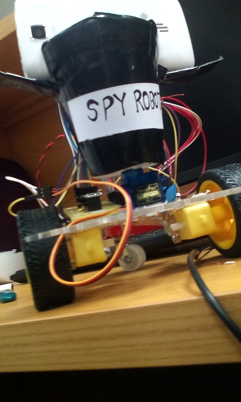
LETS BEGIN THE JOURNEY OF MAKING A SPY ROBOT………..!
Attaching the Mobile
IDownload the software of Droid Cam on your smart phone. Then download the same software on your PC or Laptop. Follow the instructions and run the software by connenting both devices through Wifi. Hence at last you see the video being recorded by your mobile on your PC or Laptop. Then attach this mobile on your Chasis accordingly that it should not fall or move during the movement of the car chasis.
Attaching the RF Module
IConnect the Receiver and Transmitter of RF module with aurdino by following its datasheet. Then attach this modules on top of Chasis.
Making a Controller
Now make a controller using appropriate switches and connect these swithes with RF module and aurdino through programming.
Doing Programming
One of the most important part of this project is that do the appropriate programming of your robot according to your circuit.
Enjoy and Watch live videos
At last assemble the car properly and control it through the controller and watch videos of your surroundings while sitting in front of you laptop ;-)
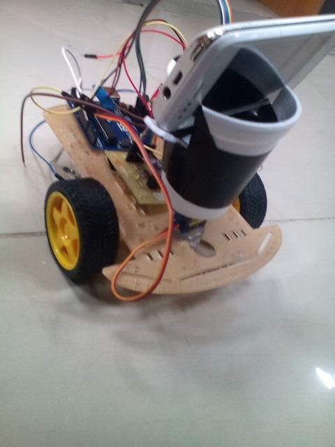
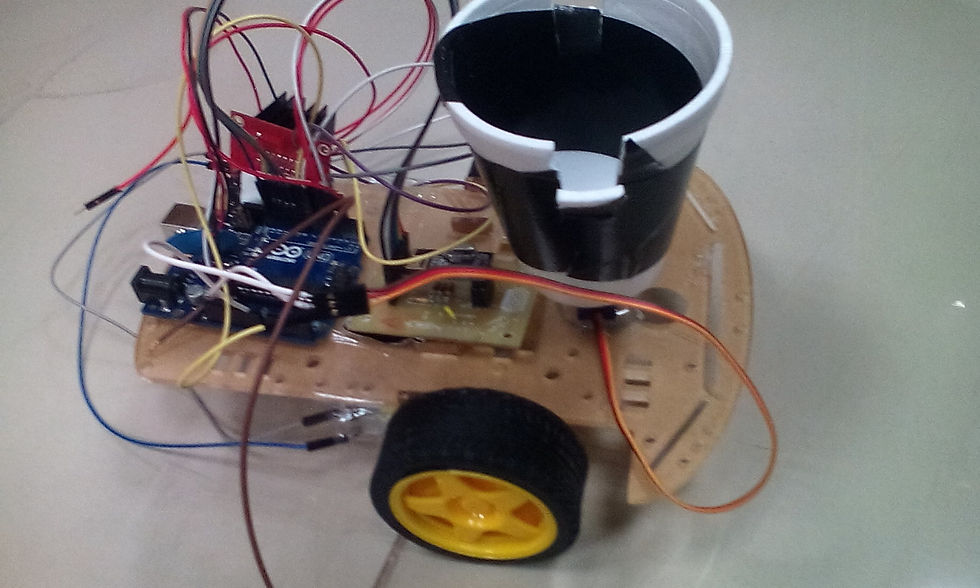
Here are some pics which we took during compeleting our Spy Robot.
Components and Software needed
NAMES
Arduino UNO board
Data Cable
Jumper Wires
Car Chasis
Motors
Wheels
Fully charged 9V battery
Wire cutter/stripper
L298 (Dual H-Bridge)
based motor driving module
Nuts and Bots
Touch Mobile
RF sensor with remote control
Droid Cam Software (Installed in PC and Mobile)
Auruino Software (Installed in PC)
Car Chassis
Gear Motors
Car Tires
Speed Encoders
Fastener
Screwdriver
Battery Box (Battery is not included)
screws and nuts
It is a very interesting Project. Just gather all the componebts and start builiding you own Spy Robot.